| Solar
Powered Picaxe Microbot (Vibrobot)
|
|||
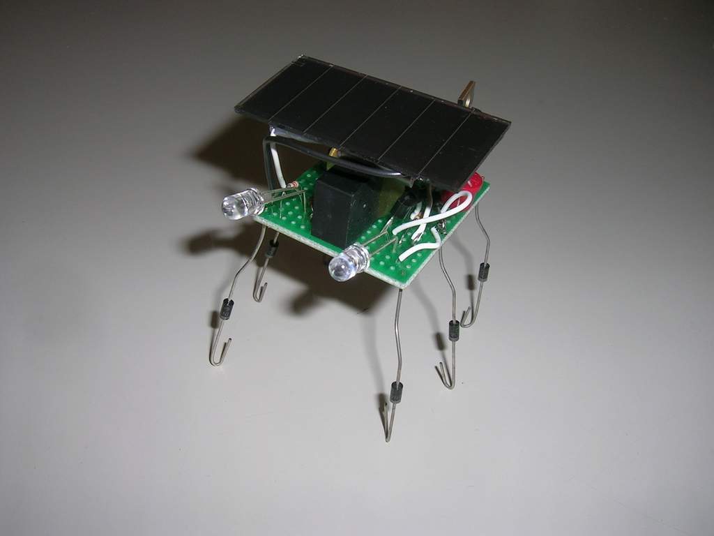
(click image for better view) Introduction: This is a small solar powered progammable robot. It's
design was inspired by BEAM
robots, but whereas those devices are usually entirely hardware
based, I favor systems which rely on software. Allowing programmability,
however basic, introduces a whole new level of flexibility.
Hardware, Parts, and Assembly The basic hardware includes the following features:
The parts used are as follows:
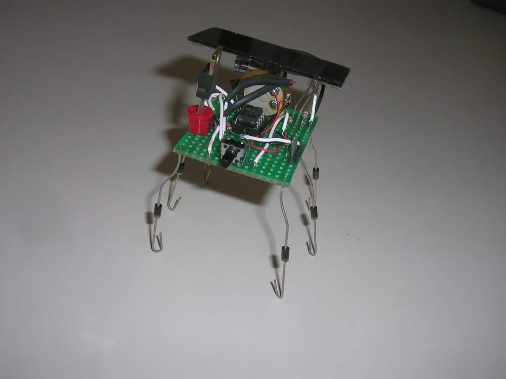
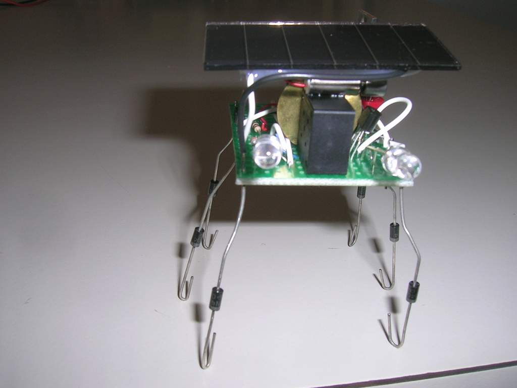
The parts are connected as depicted in this schematic. Assembly on a small piece of stripboard was compact, but not too daunting. The nice square shape of the capacitor was perfect for supporting the piezo and anchoring the motor. The solar cell simply glues on top of the motor. The programming header is hard to get to once the solar cell is glued, but because it is a double-male, it can be accessed from the bottom of the board. Use medium power diodes for the legs since small-signal are easily bent when putting the robot down on a hard surface.
This progam flashes the eyes with frequency proportional to the capacitor voltage. At a predetermined voltage threshold, the microbot starts to vibrate. Once in a while (about 5% of the time), the vibrobot will play a few seconds of random tones. And if the tail switch is pressed it plays happy birthday with flashing eyes to accompany the tune.
Thoughts In building this robot, there were a few things worth noting: - Writing software where the system can terminate at any moment and restart is a slightly different mindset from normal software tasks which usually proceed with a well defined program flow. It more closely resembles interrupt driven programming with a bit of chaos. - Using random numbers on a microcontroller takes a bit of work. Whereas a psuedo-random number is almost always used in programming (e.g. a linear congruential random number generator), this doesn't work so well on a microcontroller since, without some planning, it always leads to the exact same sequence of numbers and a repetitive well-defined behavior results rather than the desired random one. In this design, I avoid this by seeding the random generator with a value based on how quickly the capacitor charges (from the sun) to a particular level. If I didn't have any external sensors, I probably would have saved the random seed in EEPROM to avoid restarting the random sequence each time, though this would have limited the lifetime of the 08M to 100,000 uses. - BEAM robots are usually very simplistic and sometimes use their IC's in unintended and even abusive ways. In this spirit, I wanted to drive the motor directly from the microprocessor and tried to do this by doubling the output drive current by conecting 2 microcontroller output pins together and then driving them identically. The resultant 50ma was still not enough to run the motor, so I ended up using a driver transistor. Even after abusing the Picaxe 08M in the testing process, however, the chip appears to be working fine. This is probably partially a result of doing everything at 2.6v (2xAA rechargeable cells) and also testimony to the robust nature of the IC's. - Using the "disablebod" command allows the microcontroller to operate at voltages right down to about 1.3v and reduces microcontroller current consumption. This is amazingly low, but comes at a cost of potentially erratic microcontroller behavior if a brownout occurs. It can be very useful in solar powered projects like this one, but watch out since driving a motor (especially without a smoothing capacitor) and microcontroller off a single supply can also lead to erratic microntroller behavior.
Licensing and Disclaimers This code is explicitly released under the GPL. And this page is licensed under a Creative Commons Attribution 2.5 License. Write me if you find this project interesting. Link to this page if you find it relevant.. Warning, robotic projects may cause loss of hair, time, money, and friends. This project is provided without any warranty and probably isn't suitable for anything. Read or write a comment on the hardware projects Back to Picaxe Projects (and info about the Picaxe microcontroller) |